171b Demonstration of the Loop Reactor Concept
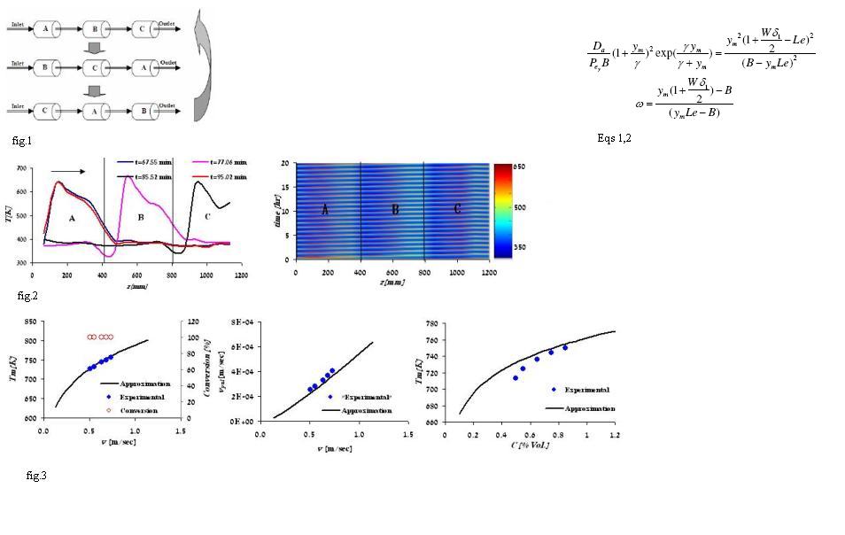
This is the first experimental show of the loop reactor concept for catalytic oxidation of low-concentration volatile organic compounds (VOC). The loop reactor is an auto-thermal system of N units organized in a loop with periodic switching of the feed and exit ports (see Fig. 1). Numerical simulations (Barrsei et al. 1999) demonstrated this concept and our analysis of the many-unit limit of this model (Sheintuch and Nekhamkina, 2005) showed the existence of two asymptotes, a low switching asymptote in which the switching velocity and the pulse velocity are synchronized, and a fast asymptote, in which the switching velocity is much faster than the front velocity. Numerical simulations revealed that the many-unit limit describes well the behavior of a system with a finite number of units. Experimental Results We report here on the behavior of such a 3-unit system for ethylene oxidation in the low switching asymptote. To expand the operating domain of that solution a scheme that controls the switching velocity in response to pulse propagation was applied. A typical spatio-temporal temperature pattern of the experimental system, (shown in Fig.2. as a color-scale plot), exhibits a moving pulse pattern. The pulse velocity is constant (period is 27 minutes) and the pulse profile, at different time after spatial translation, overlap (Fig. 2). The influence of the main operating parameters, namely, the inlet flow rate and the working temperature, has been investigated Fig.1. Scheme of the three-reactor loop system Fig.2. Spatio-temporal color-scaled temperature profile presented in the time-space plane (right). Three snapshots of the temperature pulse propagation and their overlapping profiles after two periodic spatial translations (left). Fig.3. The dependence of the maximal measured temperature and conversion (right), the measured pulse velocity on fluid velocity (middle) and dependence of measured maximal temperature on feed concentration (left). Also shown is their approximation by the model. The Analytical Approximation A simple one-dimensional (1-D) nonadiabatic model, accounting for first order kinetics, has been constructed and its analytical approximations were comparing with the experimental results (Fig. 3). The expression for the maximal dimensionless temperature (ym) and the dimensionless pulse velocity &omegaƒware given by Eq. 1-2 (Madai and Sheintuch, 2008) Eqs. 1.2 Where we use traditional notation and W is dimensionless heat transfer coefficient while &delta is the experimentally-determined pulse width. (In an adiabatic case (W=0) these equations are reduced to appropriate relations for an "ideal" front). Approximation using Eqs. 1-2 show a good agreement with experimental and numerical results (Fig. 3) . Conclusions: Comparison of this reactor with Reversed-Flow reactor will be presented: Under certain conditions the loop reactor may yield higher maximal temperature than the RF and, when deactivation cannot be avoided, it is spread evenly around the system. Yet, the loop reactor requires more valves and a feedback control. References 1. M Brinkmann, , A.A Barresi, M Vanni & Baldi G. Unsteady state treatment of very lean waste gases in a network of catalytic burners. Catalysis Today.; 47: 263-277 (1999) 2. Sheintuch & O. Nekhamkina, The asymptotes of loop reactors. AIChE Journal. 51(1): 224- 234 (2005). 3. A.Y Madai & M. Sheintuch, Demonstration of Loop Reactor Operation. AIChE Journal (sub